How GD&T Benefits Manufacturers
As consumer expectations have risen in the 21st century, so have the standards of today’s manufacturers. As an engineer, it’s not always easy to meet the demands of both. However, the processes of geometric dimensioning and tolerancing, or GD&T, can streamline the process in ways you never thought possible.
Understanding GD&T
To understand how GD&T benefits manufacturers, it’s useful to understand the ins and outs of what GD&T is and how it works.
GD&T is a language of engineering symbols used to make manufactured parts more consistent with one another and accurate to the computer-aided designs (CADs) that engineers use to conceptualize components.
The premise of GD&T was developed in 1938 when a mechanical engineer named Stanley Parker noticed that the torpedo components he was quality-checking would still work even if their dimensions were slightly incorrect. He used this information to calculate how incorrect the dimensions of a component could be while still rendering that component usable.
Parker posited that a language to calculate and describe how incorrect the dimensions of a part could be without causing the part to be unusable would allow manufacturers to increase the accuracy and efficiency of the production process. Thus, GD&T was born in 1956 from a book by Parker titled “Drawings and Dimensions.” The military then adopted the concept, and GD&T has been used widely among mechanical engineers and manufacturers in Western developed countries ever since.
How GD&T Works
GD&T designates “tolerances” for a component. A tolerance value dictates how incorrect the dimensions of a part can be while still maintaining the usability of that part. For example, if a component has a circumference of 3 inches with a tolerance of 0.3 inch, that component is still usable if the circumference measures either 3.3 or 2.7 inches.
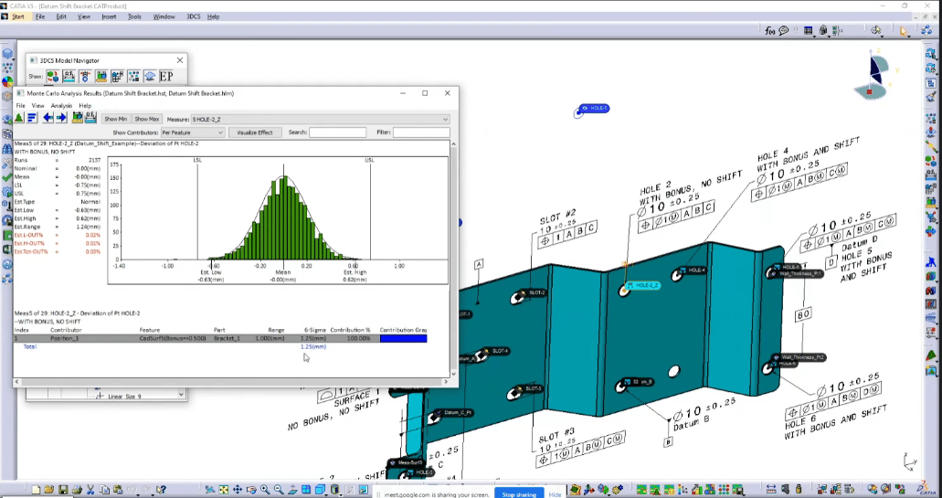
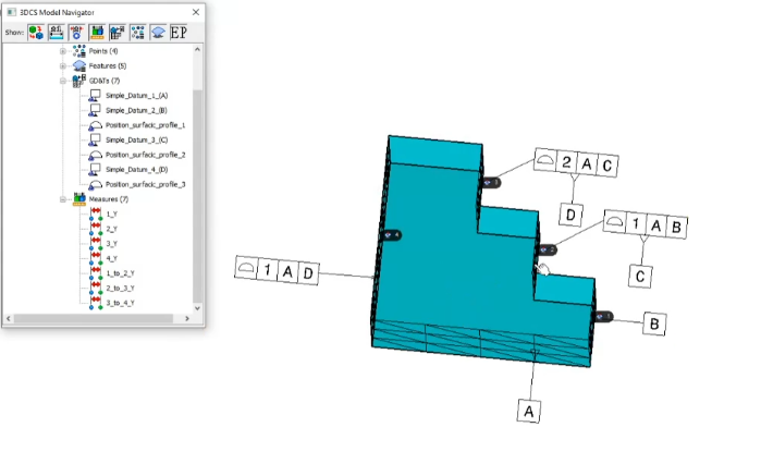
GD&T uses a datum reference frame (DRF) to designate the planes in which a component exists. Here’s how it works:
- A primary datum (a theoretical plane, point, or axis) is conceived with a minimum three-point-contact of the first feature of a part. Think of this as the starting point or zero reference to understand a component.
- A secondary datum with two minimum contact-points of the second figure of the component is established.
- A tertiary datum is decided based on a minimum one-point-contact.
These three datums make up the DRF. You can think of the DRF as a frame for a hypothetically perfect design.
True positions are then used to designate where each part would be in the DRF if the component were manufactured perfectly. In a CAD, every part has a true position of zero. Position tolerances are then used to decide how imperfectly each part can be manufactured without making the component as a whole unusable.
GD&T uses a variety of controls to dictate the dimensions and tolerances of a manufactured part. You can break down GD&T into three major areas to understand the most common controls GD&T uses:
Straightness and Flatness
These are the most straightforward GD&T controls.
- Straightness controls how straight a hypothetical line on a surface can be, and how much that line can vary in practice.
- Flatness dictates how flat a part needs to be across its entirety.
Angularity, Parallelism, and Perpendicularity
These controls are a bit more complicated.
- Parallelism dictates how close to parallel two straight lines on a part should be.
- Perpendicularity is used to designate how close to a 90-degree angle the conjunction between two aspects of a part needs to be.
- Angularity dictates the angle aspects of a part should meet at and is used for any larger or smaller than 90 degrees, while perpendicularity is only used for 90-degree conjunctions.
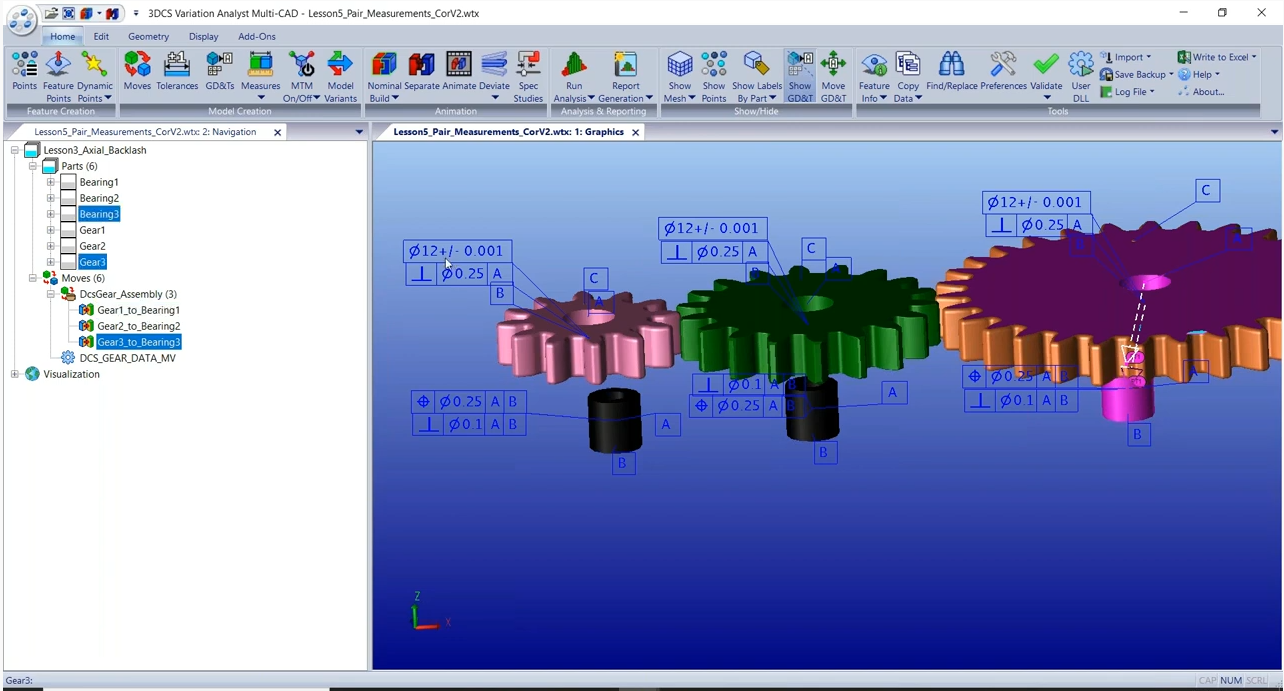
Circularity, Cylindricity, and Concentricity
These are the last significant controls for GD&T.
- Circularity controls how round a feature, such as the outside surface of a cylinder or the inside surface of a hole, should be.
- Cylindricity is specifically used to control the dimensions of cylinders, which would otherwise require an inefficient combination of circularity, straightness, and perpendicularity controls.
- Concentricity allows manufacturers to decide how consistently thick the walls of a part should be in relation to the center axis of the part.
There are a variety of other controls within GD&T, but none are as significant as those covered above. For example, least material condition (LMC) and maximum material condition (MMC) are used to specify how much material can exist within the volume of a part. However, these controls are often a by-product of other, more significant controls that already affect how much or little material can be on a part.
All of these controls correspond with various symbols that make up the “language” of GD&T. These symbols are then used in conjunction with one another to create a comprehensive representation of a part’s ideal dimensions and tolerances. This information can then be input into production tools and used to automatically create parts.
As a caveat, it’s important to note that the GD&T language remains consistent regardless of feature size (RFS). In other words, the GD&T controls and tolerances for a part remain the same even if that part is scaled up or down in size. As a result, engineers don’t have to redraw designs for upscaled or downscaled components and can more easily control tolerances in the event of a size change.
Many manufacturers are skeptical when asked to implement GD&T into their production pipeline. Often, manufacturers worry that their vendors or engineers won’t understand GD&T and that it would be too difficult to learn.
The reality is that vendors don’t necessarily need to understand GD&T, and training engineers and quality assurance (QA) professionals to understand GD&T is well worth the hassle. Here’s why:
The Benefits of GD&T for Manufacturers
GD&T benefits manufacturers in a multitude of ways:
- It saves money. Integrating GD&T with other production accuracy enhancement tools such as statistical process control (SPC) allows manufacturers to achieve cutting-edge accuracy in production. Increasing the accuracy of produced parts and components results in decreased waste, ultimately saving money for manufacturers.
- It increases customer satisfaction. With GD&T, manufacturers can create better parts and components than ever before. As a result, end products made using GD&T are as close to perfect as possible (assuming a manufacturer uses strict tolerances, of course).
- It increases collaboration between teams. Frequently, manufacturing engineers and QA professionals have trouble communicating. Typically, the confusion is a result of QA professionals not fully understanding how an engineering team wants to produce a part. GD&T avoids this by standardizing manufacturing expectations across teams. As long as engineers and QA professionals both understand GD&T, the two parties never have to worry about miscommunication over parts or components ever again. Both teams have a precise understanding of what a part should look like, enhancing collaboration and communication across departments.
- It’s easier to use than you think. Many manufacturers assume GD&T is challenging to learn or use. GD&T is incredibly intuitive, particularly for professionals used to dealing with the production process such as engineers or QA testers. GD&T also integrates well into both 2-D and 3-D CAD tools, making blending it into a production pipeline efficient and user-friendly.
Ultimately, manufacturers interested in making their production pipeline as cutting-edge, financially stable, and reliable as possible should invest in GD&T as quickly as possible. The benefits of GD&T far outweigh any negatives and allow manufacturers to accelerate their business to its full potential.