
The Industry Leading Integrated Tolerance Analysis Software
3DCS Variation Analyst is used by leading manufacturers in the aerospace, automotive, medical device, electronics and machinery industries.
As the most advanced tolerance analysis tool in the market, 3DCS Variation Analyst offers users the ability to do more than just 3D stack-ups by analyzing the relationship between their parts, and accounting for a multitude of sources of variation. This gives you the most accurate results to make important decisions about your design and manufacturing processes.
3DCS Variation Analyst simulates both part and process variation. This enables engineers to analyze their manufacturing process and how it affects both the assembly and final product functionality.
3DCS is fully integrated into the major CAD platforms : CATIA V5®, 3D Experience®, NX®, Creo®, SOLIDWORKS®, but also exisits as a Stand-Alone application that can import 3D models thanks to native or standard interfaces (STEP, IGES, …).
3DCS is developped by DCS Inc. (Dimensional Control Systems). Based in Troy, Michigan, USA, DCS is focused on the methodology of Dimensional Engineering. DCS offers best-in-class software solutions and services to manufacturing companies the world over. With over 50 years of Dimensional Engineering background, DCS continuously strives to exceed their customer’s expectations for world-class Variation Analysis and Quality Management System (QMS) software and services.
`
WHY 3DCS ?
- True 3D tolerance analysis, no over simplification linked to 1D or 2D Stack Analysis.
- Avoid costs generated by non conformities on the manufactured products discovered after production, or worse during customer utilization.
- Optimize manufacturing costs by specifying tolerance ranges as large as possible (no “over-quality”) while respecting the design specifications of the products.
- Decision helper to validate or reject derogations when receiving non conform batches of parts.
- Set Perceived Quality objectives
DESCRIPTION
3DCS Variation Analyst is the base module that allows to:
- Define the relative position of the parts in the assembly through “Moves” that describe which features locate the parts one to each other.
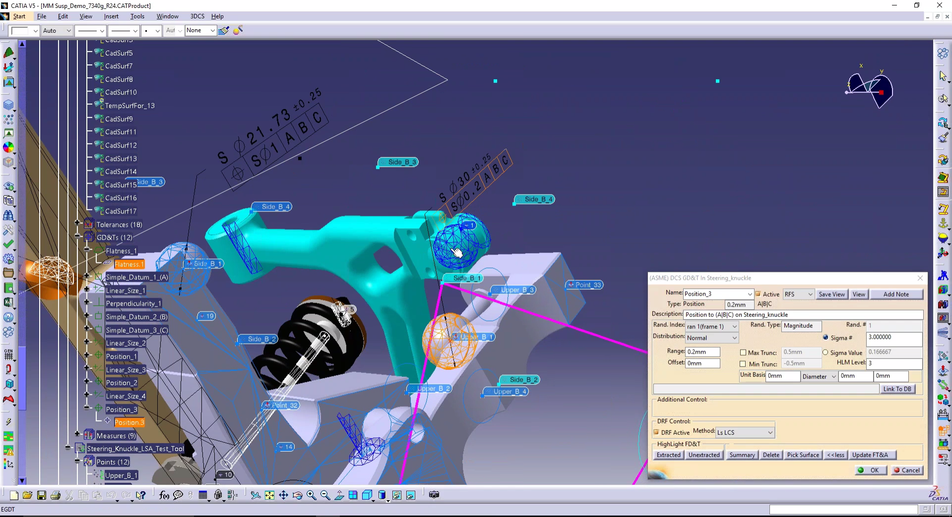
- Define the sources of variation through GD&Ts and point based tolerance.
- Import 3D GD&T from the CAD system (FTA, PMI, etc…)
- Edit the tolerance ranges imported from the CAD system without changing the source values in order to simulate all the desired scenarios
- Specify the Measurements that must be checked, thus defining the desired output from the analysis (gaps, flushes, angles, interferences, geometric tolerances…).
- Simulate the variations of each Measurement either through
o A Monte Carlo simulation that will virtually build a large number of assemblies after varying parts feature dimensions or positions within their tolerance ranges.
o A Geofactor based analysis that uses linear equations to link the output to the input parameters. - 3DCS includes the possibility to either use standard statistical laws (normal, bi-modal, constant, uniform, Rayleigh, Pearson, etc…) to define the distribution of the variations as well as user-defined laws. In that case, measurement values coming from the actual manufacturing process can also be used.
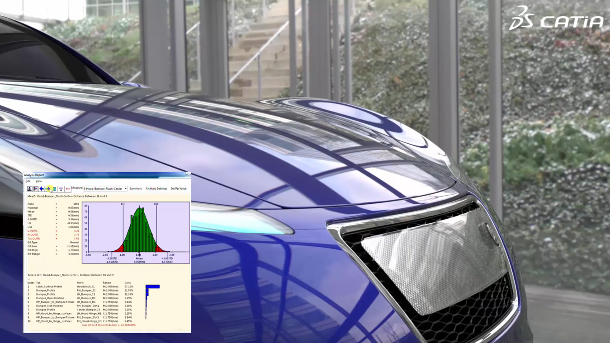
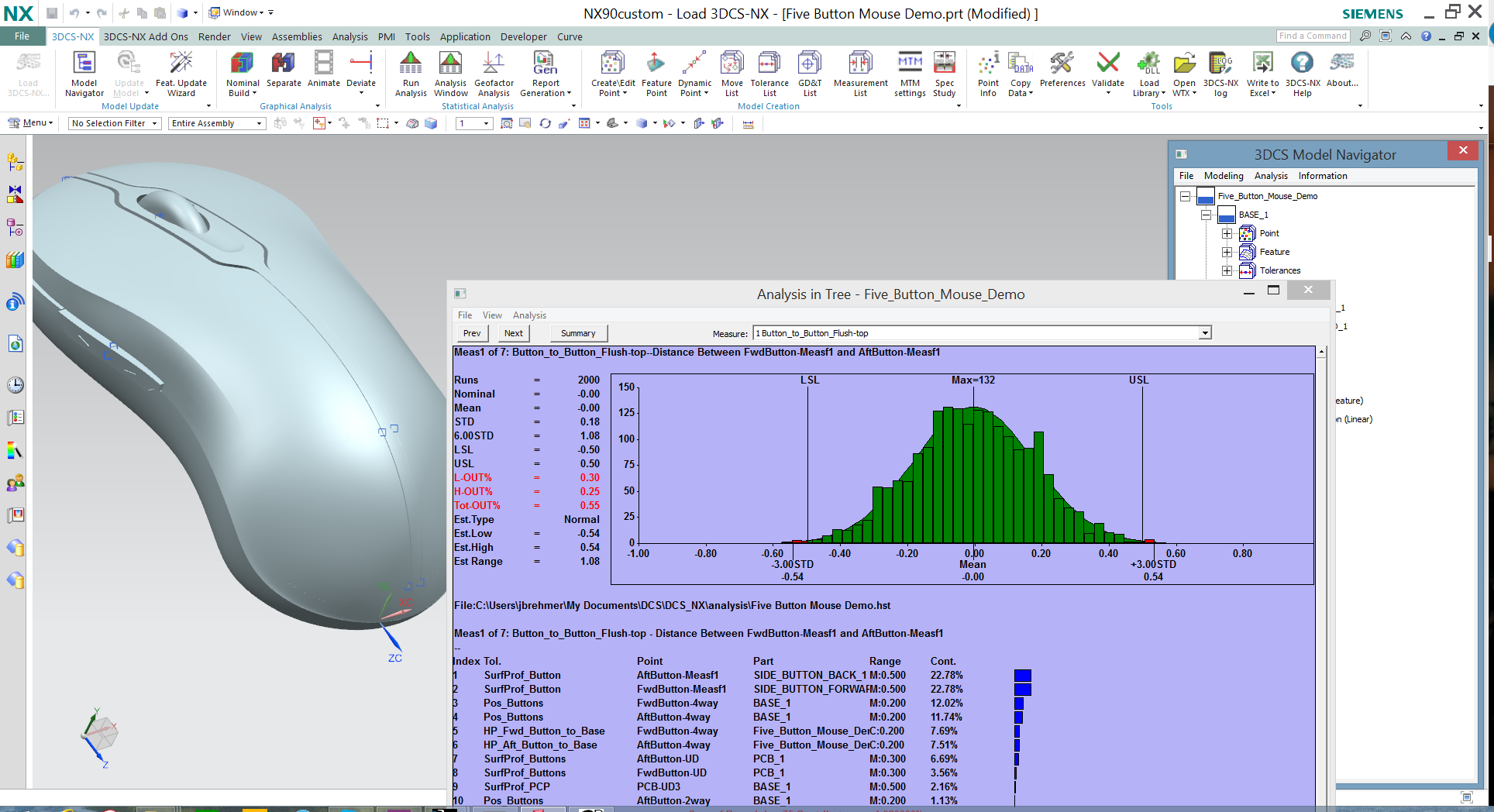
- Produce various statistical results (mean, STD, Capability, %Out of Spec, etc…) and display histograms.
- Calculate and display the contribution of each tolerance to the measurements
- Display these contributions in a tabular format sorted by order of influence, together with a feedback on the CAD geometry to get a clearer view of where the variations come from.
- The analysis results can be exported in various formats, including Excel (CSV) for the numerical values and in HTML for complete reports including graphics and tables.
- Automatic report generator in HTML, Word, Excel or PPT format. These reports will allow non experts to understand the results easily.
- Batch calculation, DOE (Design of Experiment) allowing to quickly build analysis scenarios by varying the parameters and launch several computations at a time in batch mode.
- GD&T analyser and checker to understand if all features are properly toleranced.
- Possibility for programmers to add their own routines through a C++ API.
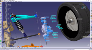
3DCS Mechanical Add-On allows to define how parts are located one to each other through kinematic joints and constraints (Revolute, Planar, Spherical, …). This module is particularly adapted to mechanisms for which the tolerance analysis must be performed in several positions. A Degree fo Freedoms counter is available to check the validity of the model definition.
Click on the image to start the video
3DCS-Compliant Modeler adds to 3DCS the possibility to take into account the deformation of the parts due to hyperstic positionning or to force or torque application (the stiffness matrix and the FEA mesh must be generate first). If a mass matrix is available, the gravity effect can also be taken into account. Thermal effect can also be added through a deformation matrix calculated outside 3DCS.
Click on the image to start the video
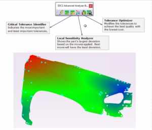
3DCS- AAO (Advanced Analyser and Optimizer) is using the Geofactors that link the Measurements variations to the parts tolerances through a linear equation system. AAO offers 5 tools:
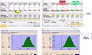
- The Analyser tool that displays a matrix with lines containg the tolerance ranges whil the coulumns list the resulting Measures and their calculated variation. At their intersection, the user can either display the Geofactor or the contribution percentage of each tolerance towards a given measurement. It is possible to modify one or several tolerance ranges and immediately see the effect on the measurement variation.
- The Optimizer tool allows to find the optimum tolerance configuration that will result in the cheapest cost for a given quality or the best quality for a given cost (this is based on the principle that the tighter a tolerance is, the more expensive it is to manufacture).
- The LSA Locator Sensitivity Analysis allows the comparison of several locating schemes by analysing the position variation of the led part as a function of the position variation of the locating surfaces of the leading part in every direction.
- CTI (Critical Tolerance Identifier) identifies the most critical tolerances to all the measurements in the model according to several criteria (Out-of Specs, Cp, …).
- SBS (Simulation Based Sensitivity) performs sentitiviy analyses by varying the input parameters and launching MonteCarlo simulations for each new combination. This allows to better process non linear models, and to detect multi-contributors sensitivities.
Click on the image to start the video
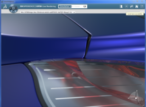
3DCS-SpecStudy is a tool that allows the user to visualize scenarios combining gaps and flushes variations. This module can work with photo-realistic rendering tools built-in your CAD system (CATIA, CREO, NX, SolidWorks) but it also allows to export both the geometry and the scenarios to third party software like 3DEXCITE DELTAGEN, Keyshot, Design Studio, etc… for a very high quality rendering. Spec Study is supplied free of charge with 3DCS-Variation Analyst when used with the CAD built-in rendering tools, but requires and extra module (Visualization Export) to be able to export to the external rendering tools.
Click on the image to start the video
3DCS- Visualization Export allows to export the geoemtry and scenarios created with Specs Study in order to visualize them in the high quality photo-rendering tools like 3D EXCITE DELTAGEN, Design Studio, Keyshot…
300 Chemin de l'Enclos
13100 Aix en Provence, FRANCE
+33 (0)9 54 50 99 90
info@hitex-international.com
Follow us on social network !
Privacy police