Comment la cotation 3D (GD&T) peut-elle aider les industriels
Les exigences des consommateurs augmentant régulièrement, il est nécessaire pour les industriels d’améliorer sans cesse leurs standards de fabrication. Le processus de cotation 3D peut faciliter ce processus d’une façon inimaginable jusque là.
Comprendre les GD&T
Pour comprendre comment l’utilisation des GD&T peut aider les industriels, il est nécessaire de comprendre les tenants et les aboutissants de cette technique et comment elle fonctionne.
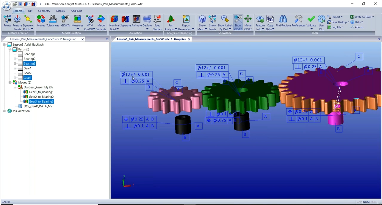
GD&T est un langage comprenant des symboles permettant de rendre les pièces fabriqués plus cohérentes entre elles et plus proches du modèle CAO que les ingénieurs utilisent pour conceptualiser les pièces.
Les prémices des GD&T remontent à 1938 lorsqu’un ingénieur en mécanique, Stanley Parker, remarqua que les composants de la Torpedo dont il vérifiait la qualité pouvaient fonctionner même si leurs dimensions étaient légèrement incorrectes. Il chercha alors à calculer l’erreur maximum acceptable sur le composant pour qu’il puisse tout de même être utilisé.
Parker se dit qu’ un langage permettant de décrire et quantifier les défauts maximums qu’une pièce pourrait présenter tout en restant utilisable, permettrait aux industriels d’augmenter la précision et l’efficacité de leur processus de production. Les langage GD&T naquit ainsi en 1956 dans un livre écrit par Parker dont le titre était « Drawings and Dimensions. » L’industrie militaire adopta le concept en premier et ce langage a depuis été utilisé par les ingénieurs et fabricants du monde entier.
Comment les GD&T sont-ils définis ?
Les GD&T désignent les « tolérances » d’un composant. La valeur de la tolérance quantifie la variation maximum des dimensions d’une pièce lui permettant de rester utilisable. Par exemple si une pièce a une circonférence de 100mm avec une tolérance de 2mm, elle restera utilisable si la circonférence est comprise entre 99 et 101mm.
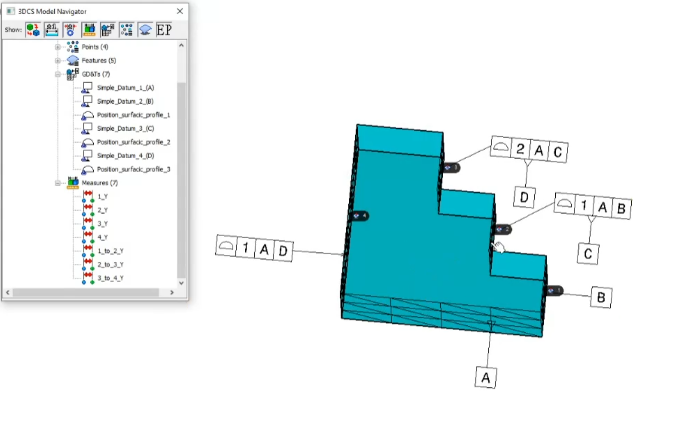
GD&T utilise un système de références pour désigner les éléments géométriques par rapport auxquels le composant est positionné. En voici le principe
- Une référence primaire (un plan un axe ou un point théorique) est défini avec au minimum un contact avec 3 points d’une surface de la pièce.
- Une référence secondaire avec un minimum de 2 points de contact avec une surface de la pièce est établie
- Une référence tertiaire est ensuite établie avec au moins un point de contact
Ces 3 références forment le système de références (DRF). On peut assimiler ce DRF à un cadre pour une pièce hypothétiquement parfaite.
Des posiitons réelles sont ensuite utilisées pour définit où chaque élément devrait se trouver par rapport au DRF si le composant était fabriqué de façon parfaite. Dans un modèle CAO chaque élément a une position nominale à zéro. Des tolérances de positon sont utilisée afin de définir avec quel défaut maximum cette position peut avoir sur la pièce fabriquée pour qu’elle remplisse quand même sa fonction.
GD&T uses a variety of controls to dictate the dimensions and tolerances of a manufactured part. You can break down GD&T into three major areas to understand the most common controls GD&T uses:
Straightness and Flatness
These are the most straightforward GD&T controls.
- Straightness controls how straight a hypothetical line on a surface can be, and how much that line can vary in practice.
- Flatness dictates how flat a part needs to be across its entirety.
Angularity, Parallelism, and Perpendicularity
These controls are a bit more complicated.
- Parallelism dictates how close to parallel two straight lines on a part should be.
- Perpendicularity is used to designate how close to a 90-degree angle the conjunction between two aspects of a part needs to be.
- Angularity dictates the angle aspects of a part should meet at and is used for any larger or smaller than 90 degrees, while perpendicularity is only used for 90-degree conjunctions.
Circularity, Cylindricity, and Concentricity
These are the last significant controls for GD&T.
- Circularity controls how round a feature, such as the outside surface of a cylinder or the inside surface of a hole, should be.
- Cylindricity is specifically used to control the dimensions of cylinders, which would otherwise require an inefficient combination of circularity, straightness, and perpendicularity controls.
- Concentricity allows manufacturers to decide how consistently thick the walls of a part should be in relation to the center axis of the part.

There are a variety of other controls within GD&T, but none are as significant as those covered above. For example, least material condition (LMC) and maximum material condition (MMC) are used to specify how much material can exist within the volume of a part. However, these controls are often a by-product of other, more significant controls that already affect how much or little material can be on a part.
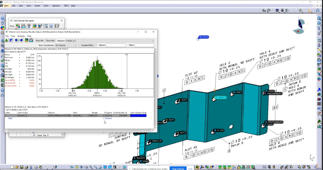
All of these controls correspond with various symbols that make up the « language » of GD&T. These symbols are then used in conjunction with one another to create a comprehensive representation of a part’s ideal dimensions and tolerances. This information can then be input into production tools and used to automatically create parts.
As a caveat, it’s important to note that the GD&T language remains consistent regardless of feature size (RFS). In other words, the GD&T controls and tolerances for a part remain the same even if that part is scaled up or down in size. As a result, engineers don’t have to redraw designs for upscaled or downscaled components and can more easily control tolerances in the event of a size change.

Many manufacturers are skeptical when asked to implement GD&T into their production pipeline. Often, manufacturers worry that their vendors or engineers won’t understand GD&T and that it would be too difficult to learn.
The reality is that vendors don’t necessarily need to understand GD&T, and training engineers and quality assurance (QA) professionals to understand GD&T is well worth the hassle. Here’s why:
The Benefits of GD&T for Manufacturers
GD&T benefits manufacturers in a multitude of ways:
- It saves money. Integrating GD&T with other production accuracy enhancement tools such as statistical process control (SPC) allows manufacturers to achieve cutting-edge accuracy in production. Increasing the accuracy of produced parts and components results in decreased waste, ultimately saving money for manufacturers.
- It increases customer satisfaction. With GD&T, manufacturers can create better parts and components than ever before. As a result, end products made using GD&T are as close to perfect as possible (assuming a manufacturer uses strict tolerances, of course).
- It increases collaboration between teams. Frequently, manufacturing engineers and QA professionals have trouble communicating. Typically, the confusion is a result of QA professionals not fully understanding how an engineering team wants to produce a part. GD&T avoids this by standardizing manufacturing expectations across teams. As long as engineers and QA professionals both understand GD&T, the two parties never have to worry about miscommunication over parts or components ever again. Both teams have a precise understanding of what a part should look like, enhancing collaboration and communication across departments.
- It’s easier to use than you think. Many manufacturers assume GD&T is challenging to learn or use. GD&T is incredibly intuitive, particularly for professionals used to dealing with the production process such as engineers or QA testers. GD&T also integrates well into both 2-D and 3-D CAD tools, making blending it into a production pipeline efficient and user-friendly.
Ultimately, manufacturers interested in making their production pipeline as cutting-edge, financially stable, and reliable as possible should invest in GD&T as quickly as possible. The benefits of GD&T far outweigh any negatives and allow manufacturers to accelerate their business to its full potential.
